
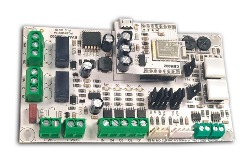
EVB-CBM002A
This evaluation board has been designed to show and test the diverse features and output/input configurations of CASAMBI CBM-002 module.
The top PCB of EVB-CBM002 incorporates a CBM-002 module and a MicroUSB input connector (5V) input.
A power-ON LED will turn on when the evaluation board is powered by the MicroUSB. EVB-CBM002 incorporates a voltage boost type converter in order to provide power for the 0-10V analog outputs.
Similar products

Low voltage, Modules
ELIZA Node + Sensor
Smart wireless Bluetooth node with sensor (PIR). All-in-one solution, one single device : Motion detection / DALI control (dimming, TW), Bluetooth mesh long range (Casambi)
ODELI Connect

Modules
CAS-ZG-40-DA-LX
CAS-ZG-40-DA-LX. Wireless Control for DALI luminaires. Casambi to DALI control device for street lighting. Compact base format compatible with Zhaga. Allows control of up to 64 DALI LED drivers, 8 short addresses, and 8 groups. Light sensor incorporated.
ELECTRÓNICA OLFER
![]()

Modules
SD240NIBLE5CH10 240W STRIP CONTROLLER 12/24V 10A
Smart Dimmable Strip Controller
Lumens Technologies Pvt Ltd

Modules
eldoLED BT-L1E-1W1
Casambi control module for eldoLED LED drivers (200+ models), model with integrated antenna, for pre-wired drivers. For white dimming and Tunable White.
eldoLED
![]()